LTC1966
21
1966fb
applicaTions inForMaTion
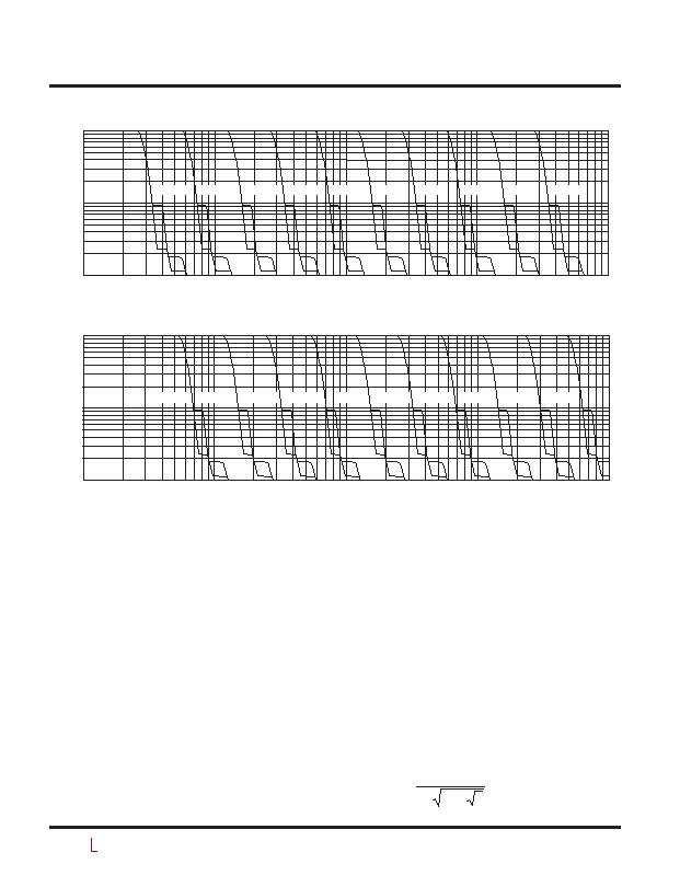
Although the settling times for the post filtered configu-
rations shown on Figures 19 and 20 are not that much
different from those with a single capacitor, the point of
using a post filter is that the settling times are far better
for a given level peak error. The filters dramatically reduce
the low frequency averaging ripple with far less impact
on settling time.
Crest Factor and AC + DC Waveforms
In the preceding discussion, the waveform was assumed
to be AC-coupled, with a modest crest factor. Both as-
sumptions ease the requirements for the averaging
capacitor. With an AC-coupled sine wave, the calculation
engine squares the input, so the averaging filter that
follows is required to filter twice the input frequency,
making its job easier. But with a sinewave that includes
DC offset, the square of the input has frequency content
at the input frequency and the filter must average out
that lower frequency. So with AC + DC waveforms, the
required value for C
AVE
should be based on half of the
lowest input frequency, using the same design curves
presented in Figures 6, 8, 17 and 18.
Crest factor, which is the peak to RMS ratio of a dynamic
signal, also effects the required C
AVE
value. With a higher
crest factor, more of the energy in the signal is concen-
trated into a smaller portion of the waveform, and the
averaging has to ride out the long lull in signal activity.
For busy waveforms, such as a sum of sine waves, ECG
traces or SCR chopped sine waves, the required value for
C
AVE
should be based on the lowest fundamental input
frequency divided as such:
f
f
CF
DESIGN
INPUTMIN
=
( )
"
3
2
Figure 20. Settling Time with DC Accurate Post Filter
Figure 19. Settling Time with Buffered Post Filter
SETTLING TIME (SEC)
0.01
0.1
1
10
1
0.1
10
100
1066 F14
C = 100礔
C = 47礔
C = 22礔
C = 10礔
C = 4.7礔
C = 2.2礔
C = 1.0礔
C = 0.47礔
C = 0.22礔
C = 0.1礔
SETTLING TIME (SEC)
0.01
0.1
1
10
1
0.1
10
100
1066 F20
C = 100礔
C = 47礔
C = 22礔
C = 10礔
C = 4.7礔
C = 2.2礔
C = 1.0礔
C = 0.47礔
C = 0.22礔
C = 0.1礔
发布紧急采购,3分钟左右您将得到回复。
相关PDF资料
LTC1967IMS8#TRPBF
IC CONVERTER RMS-DC PREC 8MSOP
LTC1968IMS8#TRPBF
IC CONVERTER RMS-DC PREC 8MSOP
LTC3100EUD#TRPBF
IC REG BUCK/BOOST/LINEAR 16-QFN
LTC3104IMSE#TRPBF
IC REG DL BCK/LINEAR SYNC 16MSOP
LTC3445EUF#TRPBF
IC REG TRPL BUCK/LINEAR 24-QFN
LTC3446IDE#PBF
IC REG TRPL BCK/LINEAR 14-DFN
LTC3537EUD#TRPBF
IC REG DL BST/LINEAR SYNC 16-QFN
LTC3541EDD#TRPBF
IC REG DL BCK/LINEAR SYNC 10-DFN
相关代理商/技术参数
LTC1967CMS8
功能描述:IC CONVERTER RMS-DC PREC 8MSOP RoHS:否 类别:集成电路 (IC) >> PMIC - RMS 至 DC 转换器 系列:- 标准包装:46 系列:- 电流 - 电源:1.2mA 电源电压:±18 V,36 V 安装类型:表面贴装 封装/外壳:16-SOIC(0.295",7.50mm 宽) 供应商设备封装:16-SOIC W 包装:管件
LTC1967CMS8#PBF
功能描述:IC CONVERTER RMS-DC PREC 8MSOP RoHS:否 类别:集成电路 (IC) >> PMIC - RMS 至 DC 转换器 系列:- 标准包装:46 系列:- 电流 - 电源:1.2mA 电源电压:±18 V,36 V 安装类型:表面贴装 封装/外壳:16-SOIC(0.295",7.50mm 宽) 供应商设备封装:16-SOIC W 包装:管件
LTC1967CMS8#TR
功能描述:IC CONVERTER RMS-DC PREC 8MSOP RoHS:否 类别:集成电路 (IC) >> PMIC - RMS 至 DC 转换器 系列:- 标准包装:46 系列:- 电流 - 电源:1.2mA 电源电压:±18 V,36 V 安装类型:表面贴装 封装/外壳:16-SOIC(0.295",7.50mm 宽) 供应商设备封装:16-SOIC W 包装:管件
LTC1967CMS8#TRPBF
功能描述:IC CONVERTER RMS-DC PREC 8MSOP RoHS:是 类别:集成电路 (IC) >> PMIC - RMS 至 DC 转换器 系列:- 标准包装:46 系列:- 电流 - 电源:1.2mA 电源电压:±18 V,36 V 安装类型:表面贴装 封装/外壳:16-SOIC(0.295",7.50mm 宽) 供应商设备封装:16-SOIC W 包装:管件
LTC1967CMS8PBF
制造商:Linear Technology 功能描述:RMS-DC converter, LTC1967 40kHz MSOP
LTC1967IMS8
功能描述:IC CONVERTER RMS-DC PREC 8MSOP RoHS:否 类别:集成电路 (IC) >> PMIC - RMS 至 DC 转换器 系列:- 标准包装:46 系列:- 电流 - 电源:1.2mA 电源电压:±18 V,36 V 安装类型:表面贴装 封装/外壳:16-SOIC(0.295",7.50mm 宽) 供应商设备封装:16-SOIC W 包装:管件
LTC1967IMS8#PBF
功能描述:IC CONVERTER RMS-DC PREC 8MSOP RoHS:是 类别:集成电路 (IC) >> PMIC - RMS 至 DC 转换器 系列:- 标准包装:46 系列:- 电流 - 电源:1.2mA 电源电压:±18 V,36 V 安装类型:表面贴装 封装/外壳:16-SOIC(0.295",7.50mm 宽) 供应商设备封装:16-SOIC W 包装:管件
LTC1967IMS8#TR
功能描述:IC CONVERTER RMS-DC PREC 8MSOP RoHS:否 类别:集成电路 (IC) >> PMIC - RMS 至 DC 转换器 系列:- 标准包装:46 系列:- 电流 - 电源:1.2mA 电源电压:±18 V,36 V 安装类型:表面贴装 封装/外壳:16-SOIC(0.295",7.50mm 宽) 供应商设备封装:16-SOIC W 包装:管件